Optical fiber polishing is a critical process in fiber optic connector manufacturing and cable assembly. Although an optical fiber is extremely small, its polished end face directly affects the quality of the optical connection.
For manufacturers working with SC, LC, FC, ST, MU, MPO and other fiber optic connectors, the polishing process must control not only surface scratches but also end-face geometry, fiber height, apex offset and radius of curvature.
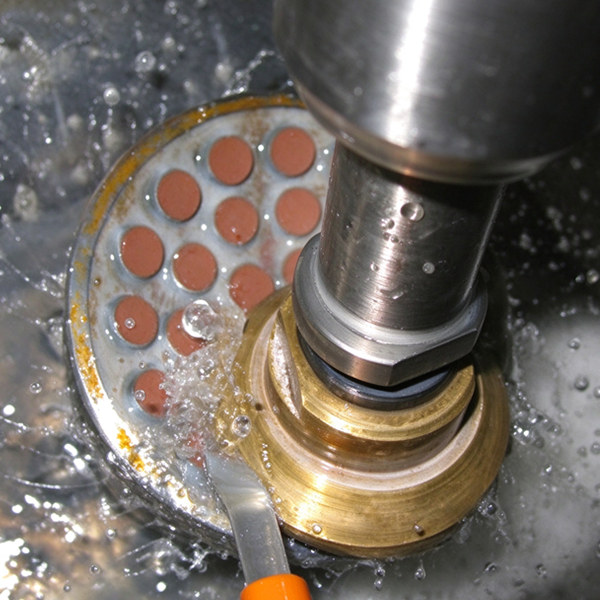
A typical fiber connector polishing process includes fiber stripping, cleaning, ferrule termination, rough grinding, fine grinding, final polishing, cleaning and end-face inspection.
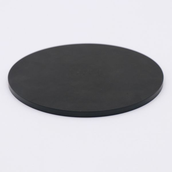
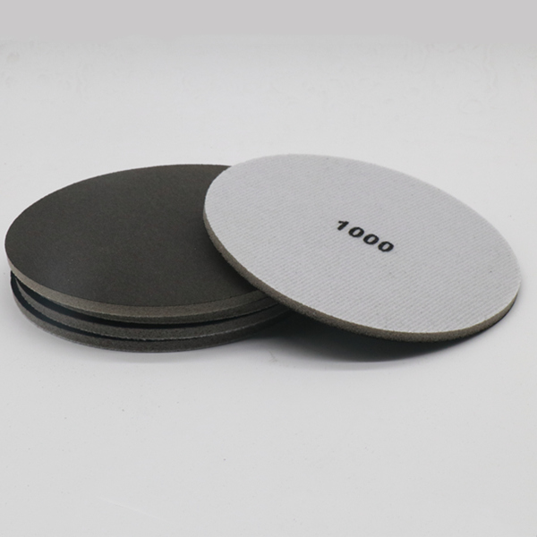
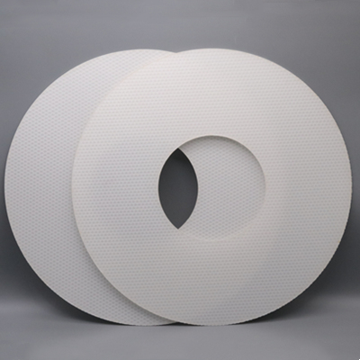
The choice of diamond polishing film, polishing pad, polishing slurry, polishing machine and connector fixture also affects the consistency of the finished connector.
This guide explains how optical fiber end faces are polished, how UPC and APC polishing differ, how to select polishing consumables, and how to troubleshoot common fiber polishing defects.
What Is Optical Fiber Polishing?
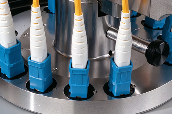
Optical fiber polishing is the controlled grinding and finishing of an optical fiber and ferrule end face to achieve the required surface finish and geometry.
In a typical connector assembly, the optical fiber is inserted into a ceramic ferrule and fixed with epoxy. After curing, excess fiber and adhesive must be removed. The ferrule and fiber end face are then progressively polished using different abrasive grades.
The objective is not simply to produce a visually smooth surface.
A production fiber polishing process needs to control:
- Fiber height
- Fiber undercut or protrusion
- Radius of curvature
- Apex offset
- End-face angle
- Surface scratches
- Pits and chips
- Surface contamination
- Insertion loss
- Return loss
Connector end-face geometry can be influenced by polishing films or other polishing media, polishing fixtures, applied pressure and polishing time.
Therefore, fiber connector polishing should be treated as a controlled process rather than simply a surface finishing operation.
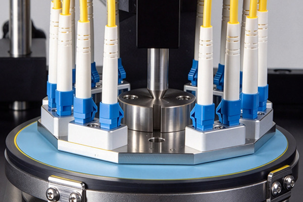
Fiber End-Face Polishing vs. Fiber Side Polishing
Optical fiber polishing can generally be divided into two different processing categories.
1. Fiber End-Face Polishing
End-face polishing is the most common type used in fiber optic connector manufacturing.
The objective is to create a controlled connector end face that allows the optical fibers to establish the required physical contact when connectors are mated.
Typical applications include:
- Fiber optic connectors
- Fiber optic patch cords
- Pigtails
- Ferrules
- Fiber arrays
- MPO/MTP connectors
- Optical transceiver assemblies
- Laboratory optical components
Common connector types include:
The polishing process can produce different end-face geometries, including PC, UPC and APC.
2. Fiber Side Polishing
Side polishing is a different process in which material is removed from the side of an optical fiber rather than its end face.
Depending on the application, side polishing may involve:
- Mechanical grinding
- Laser processing
- Chemical etching-assisted polishing
- Thermal stretching
These techniques can be used for specialized optical structures, sensing devices and micro/nano fiber fabrication.
For most fiber connector manufacturers, however, end-face polishing is the primary production process.
What Abrasives Are Used for Fiber Optic Polishing?
Different abrasive materials are used at different stages.
Diamond Polishing Film
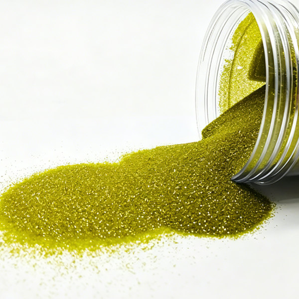
Diamond film is commonly used for material removal and fine grinding.
Typical grades can include:
- 30 μm
- 15 μm
- 9 μm
- 5 μm
- 3 μm
- 1 μm
- Sub-micron grades
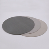
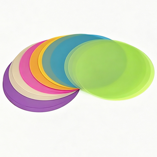
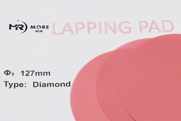
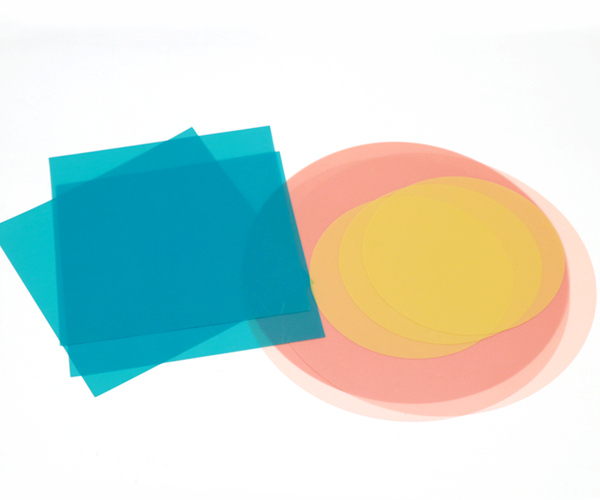
Diamond and silicon carbide films are available in multiple abrasive sizes, illustrating the importance of progressive abrasive selection in connector finishing.
Silicon Carbide Polishing Film
Silicon carbide can be used for relatively aggressive material removal and intermediate grinding.
Aluminum Oxide
Aluminum oxide polishing films may be used for intermediate or finishing applications depending on the process.
Silica or Cerium Oxide
Fine polishing media can be used for final surface finishing when the process requires very low surface roughness.
The actual abrasive sequence should be validated against the specific connector, ferrule, polishing machine and required end-face specification rather than applying one sequence to every application.
How to Select a Fiber Optic Polishing Machine
For production applications, selecting a polishing machine is not simply a question of rotational speed.
A manufacturer should consider:
1. Connector Type
For example:
- SC
- LC
- FC
- ST
- MU
- MPO/MTP
- Fiber array
2. UPC or APC Geometry
The machine and fixture must support the required connector geometry.
3. Production Volume
Laboratory and low-volume production may require only a small-capacity machine.
High-volume connector production requires higher fixture capacity and repeatable automated process control.
4. Pressure Control
Stable pressure is important because polishing pressure affects material removal and end-face geometry.
5. Polishing Motion
The machine’s rotation/revolution system affects abrasive distribution and material removal across the connector end face.
6. Fixture Compatibility
The polishing fixture must correctly support the connector or ferrule.
For production, the fixture is just as important as the machine itself.
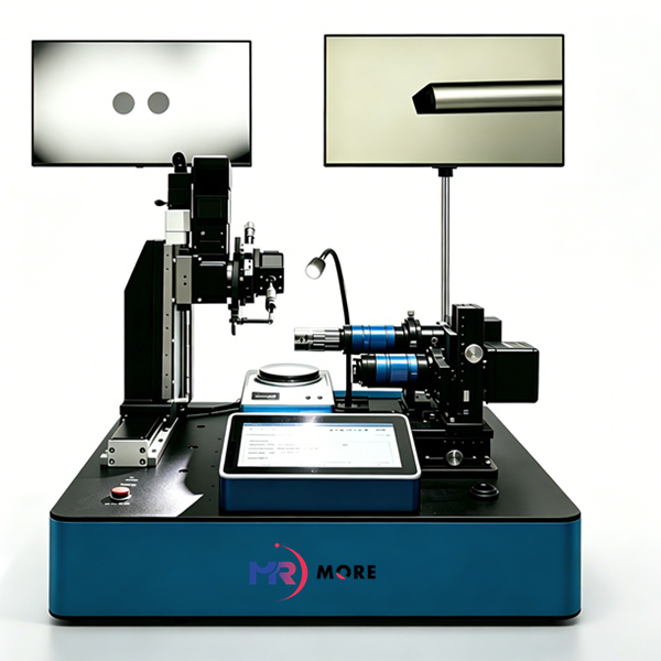
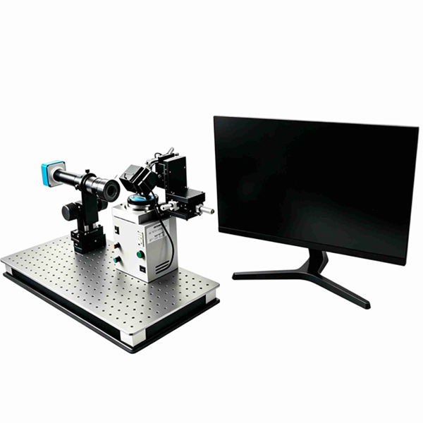
Common Fiber Connector Polishing Problems
Deep Scratches
Possible causes
- Abrasive contamination
- Incorrect abrasive sequence
- Reusing contaminated polishing film
- Inadequate cleaning
- Excessive polishing pressure
Recommended process checks
Check the polishing film, pad, workholder and cleaning procedure before increasing the polishing time.
Fiber Undercut
Fiber undercut means the fiber surface is lower than the surrounding ferrule surface.
Possible causes include:
- Excessive pressure
- Incorrect pad hardness
- Excessive polishing time
- Improper abrasive selection
- Incorrect polishing process
High Apex Offset
Possible causes include:
- Uneven polishing pressure
- Incorrect fixture alignment
- Pad deformation
- Uneven abrasive distribution
- Incorrect polishing parameters
Excessive Fiber Protrusion
Possible causes include:
- Insufficient polishing
- Incorrect material-removal sequence
- Improper ferrule/fiber preparation
- Incorrect polishing time
Poor Return Loss
Poor return loss may be related to:
- Incorrect APC geometry
- Surface defects
- Fiber contamination
- Excessive scratches
- Incorrect end-face geometry
- Inadequate final polishing
Therefore, simply increasing polishing time is not always the correct solution.
The entire process should be checked from fixture alignment → pressure → abrasive → pad → cleaning → inspection.
Fiber Optic Connector Polishing for Mass Production
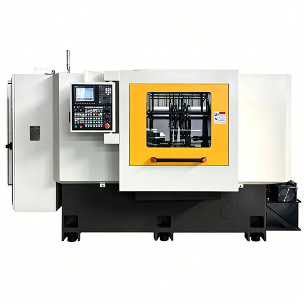
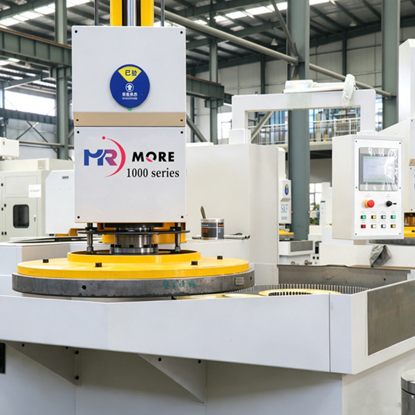
For high-volume connector manufacturing, polishing equipment must provide repeatable pressure, motion and process timing.
Modern production polishers may provide:
- Multiple connector positions
- Programmable polishing processes
- Controlled polishing pressure
- Adjustable rotation and revolution
- Dedicated polishing fixtures
- Process data management
- Automatic or semi-automatic clamping
The actual machine capacity required depends on the connector type, production volume and polishing process.
Fiber Optic Polishing Consumables for Different Applications
Different applications may require different polishing processes.
| Application |
Typical Requirements |
Main Consumables |
| SC/LC UPC |
Controlled geometry and low surface defects |
Diamond film + polishing pad |
| SC/LC APC |
Controlled 8° geometry |
Diamond film + APC fixture + polishing pad |
| FC Connector |
Ferrule end-face finishing |
Diamond film + pad |
| ST Connector |
End-face finishing |
Diamond film + pad |
| MPO/MTP |
Multi-fiber geometry consistency |
Fine polishing film + controlled pad |
| Fiber Array |
Multi-fiber alignment |
Fine polishing film + compliant pad |
| Bare Fiber |
Precision end-face finishing |
Fine abrasive film + specialized holder |
The exact polishing sequence should be established through process trials rather than assuming that one recipe applies to every connector.

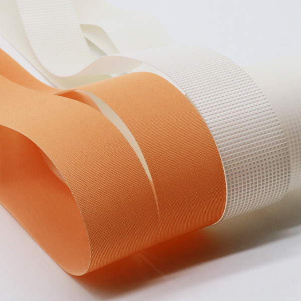 3D Structured Film (Cleaning belt for LCD panels)Flocked Pile Polishing Film for Roller Finishing and LCD Wiping
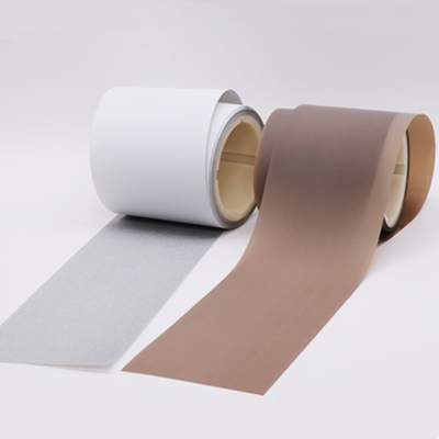 Polishing tape for repair defects and flatten protrusion points in LCD color filter process
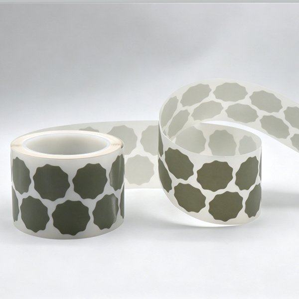 PSA Film Disc Roll for Fine Sanding and Finish of Automotive Coatings
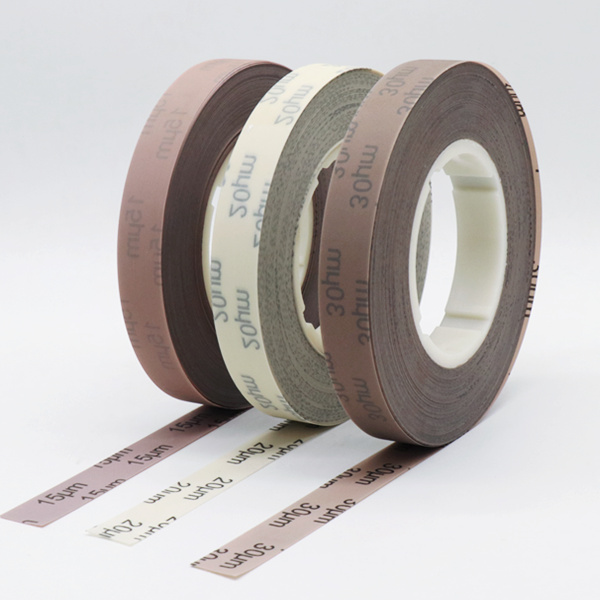 Electrostatic Coated Microfinishing Film Roll for Ultra-Fine Surface Finishing
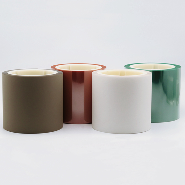 Precision Coated Diamond Roll for Fiber Optic & Microfinishing